
Let’s start by saying RS485 is an excellent communication standard. It’s designed for long distances (up to 1200 m), relatively high speed (up to 10 Mbps), and a decent number of devices (32 to 256, depending on the transceiver). However, saying that you could use these specifications doesn’t mean you should.
Length of a single branch of copper RS485 should be kept under close scrutiny. There is another word for a big copper network that extends through many floors or buildings. That word is antenna.
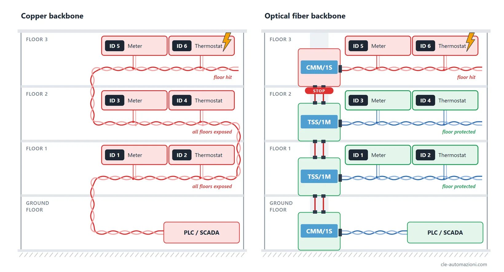
What does it mean? It means that all electrical noise going through the air can be coupled to the network, creating interference. The RS485 communication won’t necessarily stop working, as it is a pretty robust standard, but the network is exposed to many problems: lightning, ground loops, overvoltages.
One RS485 bus across several floors: where the problem starts
Between different floors of a building, there could be a few volts of ground difference. It’s not much, and many devices won’t even notice, they’ll work like a charm (some devices can withstand a bigger ground difference, but that’s another story). However, with many floors these few volts add up, and communication could be affected: a timeout or some lost packets, one or two faulty drivers. Still manageable.
Then a storm happens, and the whole bus blacks out. So, what happened?
Static electricity or a lightning strike could create a temporary ground difference of hundreds or even thousands of volts across a bus, and transceivers will break. So we need a way to make devices talk to each other without using copper wires or electricity, and the answer is optical fiber.
Splitting the bus into several branches by means of optical fiber is beneficial in 3 ways, mainly:
- Fewer devices on a single segment means that the signal voltage is higher, so the communication is more tolerant to noise. This is true when splitting the bus with optical fiber, of course, but also with RS485 repeaters.
- Shorter copper branches mean that the size of the antenna created by copper is smaller, which reduces coupled noise and interferences.
- Shorter copper branches mean that, should lightning strike close to the bus, fewer devices are at risk of being affected.
Having all the communication via fiber optics would be best, of course, but this doesn’t make much sense: it’s expensive and not really convenient from an installation standpoint.
So the widespread recommendation is to use optical fiber at least for the backbone of the network, in order to balance cost, convenience, and protection.
What an optical fiber repeater looks like
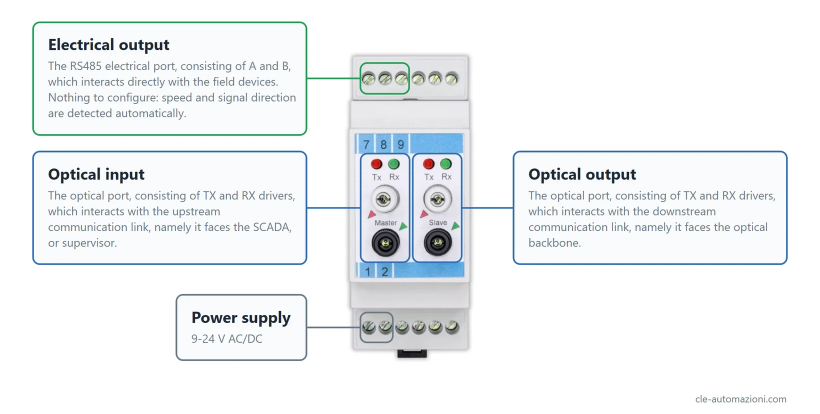
Optical fiber works point-to-point, meaning that you cannot daisy-chain multiple devices directly, so an optical fiber repeater is needed. Let’s take TSS/1M as an example: it has 3 sections, each one having a precise job.
How a request is handled
- In the video the PLC polls three devices, one at a time: ID 8 on floor 3, ID 4 on floor 2, ID 3 on floor 1.
- The PLC sends the request on its RS485 cable. The CMM/1S turns it into light and sends it up the fiber.
- The first repeater receives the packet on its Optical Input port.
- At the same time the repeater does two things: it retransmits the packet on the Optical Output port to the next floor and on the Electrical Output RS485 bus of its floor.
- The next floor does the same, and so on up to the last floor.
- Result: the request reaches every bus on every floor.
- All devices see the packet, only the one with the right address accepts it: the others ignore it, as on a normal RS485 bus.
- The added delay is minimal: about 100 ns per repeater, typically.
- Numeric example: with 10 repeaters the total delay is 1 µs, less than one bit at 250 kbps (4 µs). For the protocol the chain is invisible.
- Seen from the PLC standpoint, it is like one electrical RS485 bus across the whole building.
- Replies travel one way only. A packet coming in from the Electrical Output is never forwarded to the Optical Output, otherwise the bus would be flooded. This may seem like a small detail, but it is what makes this topology actually work.
Fiber and grounds: ground loops, noise and lightning
Optical fiber is made of glass or plastic, so it doesn’t conduct electricity: that’s the whole point of using it. In the above example, the bus is not electrically connected between floors, so each one is completely independent, and the advantages all lead to the same result: a more robust communication.
The main benefits of fiber are: no ground loops, immunity to noise, immunity to lightning.
Loops
When two points at a different potential are connected by a conductor, current flows. No way around this. Ground is used as a reference, but ground doesn’t mean much in itself, as the “same” ground could differ even by tens of volts in a single building, hundreds between different buildings.
Keeping these two concepts in mind, what is a ground loop exactly? When different grounds are connected together, and their potential is not the same, current flows, as it tries to balance the potential. This is a problem for two reasons: current generates a magnetic field around the wire, and if it’s strong enough it can couple to the bus wires (A and B) and create interferences. Moreover, the RS485 standard allows common mode voltage from −7 V to +12 V, although our transceivers can withstand up to ±25 V. If the ground difference across the bus is higher than this voltage, the communication will simply not work. If the common mode is way higher than a few tens of volts (even temporarily, due to an overvoltage for example), the transceivers will be irreversibly damaged.
Noise
Pretty straightforward: cellular networks and WiFi are noise, from the point of view of the RS485 bus communication. Inverters, motors, and pumps are also noise. It can couple to the copper wires and induce a current, which generates a voltage.
This problem can be heavily mitigated by twisting the A/B wires (especially if the noise is low and continuous, like cellular and WiFi), and most cables are currently sold already twisted. Sometimes, though, the noise is so strong that the only solution is optical fiber isolation.
Lightning
When lightning strikes a spot, it spreads quickly over electrical conductors, such as copper wires. There are some ways to mitigate the surge consequences, but the only real blocker of such an atmospheric event is optical fiber, as it is a perfect insulator.
It is fairly obvious, but it’s better to address this: if the devices share the same supply, they are not isolated, and lightning can spread through those wires even if the RS485 bus is protected. It’s necessary to have different supplies for different branches. Also obvious, also better to address this: the branch hit by lightning stays exposed, optical fiber only stops propagation between different branches.
Practical example: what you need for a 3-floor hotel
Which fiber to choose
The choice depends mainly on the distance between repeaters.
| Fiber | Connector | Max distance | Speed | Products |
|---|---|---|---|---|
| Glass Multi-Mode Fiber | Bayonet ST | 2000 m | 0-250 kbps | TVV/1M, CMM/1V |
| Plastic Optical Fiber (POF) | Screw | 100 m | 0-250 kbps | TSS/1M, CMM/1S |
| Hard Clad Silica (HCS) | Versatile Link | 500 m | 0-40 kbps | TQQ/1M, CMM/1Q |
Rule of thumb: inside the hotel, with repeaters within 100 m, plastic (POF) is enough. You cut and fit it on site, no extra tooling needed. For separate buildings, choose glass fiber.
Bill of Materials
- PLC or the server of your choice on the ground floor, usually close to the reception, 3 floors with RS485 devices.
- 1 CMM/1S on the ground floor, 1 TSS/1M on floor 1, 1 TSS/1M on floor 2, 1 CMM/1S on floor 3.
- Optical fiber: one dual channel fiber (TX and RX) between floors, for example POF/2.
- Power supply: one supply (transformer or switching) per floor.
- On each floor bus: 120 Ω termination at the end (or ends, depending on the topology).
- For more floors: add one TSS/1M per extra floor.
Installation checklist
- The Optical Input faces the server, the Optical Output the next floor.
- On each optical link the TX of one unit goes to the RX of the other.
- Plastic fiber: clean cut and fiber pushed fully into the connector.
- Check the maximum distances in the table for each section, and respect the maximum bend radius.
- Each Electrical Output branch is a separate RS485 bus: it needs its own termination.
- One supply per RS485 branch, never one for all.
FAQ
- Why should I use this topology? You can see it like an insurance on your bus. You pay a small fee at the beginning to make it more robust and protected.
- Does the repeater slow down communication? About 100 ns per repeater, so 10 repeaters introduce about 1 µs latency, less than one bit at 250 kbps.
- Do I have to set speed or direction? They are automatic: no DIP switch setting is needed.
- What distance do plastic fiber and glass cover? POF 100 m, VersaLink HCS 500 m, glass 2000 m per section.
- Does fiber protect against lightning? It stops propagation between branches, but the hit branch stays exposed.
- Can two devices on different floors talk to each other? No, the architecture is master/slave: they talk only to the server or PLC.
Wrapping up
A fiber backbone changes little for the PLC and a lot for the installation. The protocol sees one RS485 bus across the whole building. The building sees separate copper branches, each with its own ground and its own supply, so a fault on one floor stays on that floor. The example used RS485, but the same repeaters work with RS422 and RS232, because the optical section does not care which electrical standard sits at the two ends.
Send us the number of floors, the distances between them and the protocol you use, and we tell you which repeaters and which fiber fit. The TSS/1M page has the full specifications.